![]()

Part 2
5/7/04
![]() ast issue, we
took a look at the some of the hardware used to install an Auto Meter Data Logger
in a contemporary racecar (in this case, a NHRA SS/GT Firebird). In that issue,
we showed you some of the hardware (sensors, etc) required for the hookup. What
follows is a continuation of the hook up process along with a series of installation
tips and tricks from the folks at Auto Meter.
ast issue, we
took a look at the some of the hardware used to install an Auto Meter Data Logger
in a contemporary racecar (in this case, a NHRA SS/GT Firebird). In that issue,
we showed you some of the hardware (sensors, etc) required for the hookup. What
follows is a continuation of the hook up process along with a series of installation
tips and tricks from the folks at Auto Meter.
Installation Tips & Tricks ...
Auto Meter is gaining a large following in the world of data logging devices. One of the reasons is that they offer hands-on installation tips and make the effort to service racer needs at the track. We've included a series of general installation tips from Auto Meter. There's nothing tricky here folks, but keep in mind a Data Logger is a sophisticated electronic device. You can't install one with a crescent wrench and claw hammer.
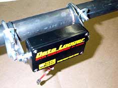
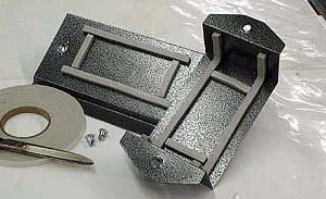 During the installation, one of the first things you have to do is fabricate a mount for the actual computer. This is a sheet metal mount fabricated for an installation. Since the car is a typical sportsman application, it doesn't have a magneto. This means that special shielding in the mount is unnecessary. As per the Auto Meter tech tips shown elsewhere in this column, weather-strip is used to isolate the computer from vibration. |
1.The computer can be mounted at any angle in the vehicle and should be supported by foam rubber or weather stripping. When properly installed, you should be able to move the unit 1/8" to 1/4" in any direction with one finger.
2. The cables included with the system are interchangeable except the remote start switch. Each cable is labeled for a specific function. The system is designed to survive an accidental misconnection for a short period of time. Damage may occur from prolonged misconnections.
3. Route all cables separate from ignition sources, plug wires, distributors, electric fuel pumps, power wires and battery cables.
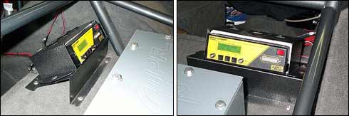
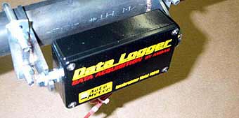
When the Data Logger is mounted in the car, it can be installed at any angle.
But remember, the front panel should be easily accessible so that you can plug
in the printer cable, adjust the settings or read the built-screen on the computer.
In this application, the computer is mounted on the rear axle kick-up on a late
model Firebird, facing rearward. In other applications, racers have found that
a mount on the roll cage close to the passenger side door works well too. Just
keep in mind that the unit should be mounted away from ignition components.
4. Do not mount the computer within three feet of any ignition sources. Examples include MSD boxes, coils, timers or distributors.
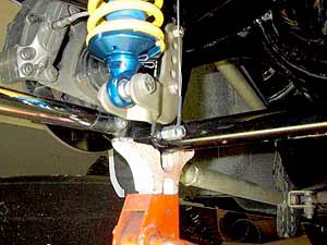
The sensor should be mounted so the cable pulls in the direction of the lower shock mount bracket or a similar location. With the weight of the car on the suspension, mount the cable to the lower mounting point with the cable extended 4-inches from the sensor. This is the neutral position of the sensor and will allow for 4-inches of travel in each direction. After mounting the sensor to the chassis and mounting the cable to the lower mounting location, slowly jack the car up, making sure that the jack is securely under the frame of the car. This insures that when the rear suspension is fully extended, the sensor is not overextended.
5. The RPM sensors were originally "unipolar" and would only respond to the silver or black (non-red) end of the trigger magnet. New versions of the data logger use different sensors that respond to either end of the magnet. The air gap between the sensor and the trigger magnet should be set between 0.100 and 0.250-inches.
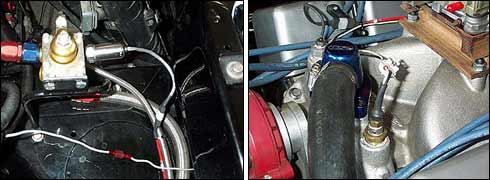
Pressure and temperature sensors are part of the normal Data Logger installation
process. The fuel pressure sensor can be installed in many different locations
(in-line, at the carburetor and so on), however a logical location is at the
fuel pressure regulator. It is also possible to mount more than one sensor in
something such as the fuel line, so that pressures can be measured before and
after the regulator or right at the carburetor. Coolant temperature sensors
are most often installed in the water cross over on the intake manifold, however
locations in cylinder heads are not uncommon.
6. The pressure sensors supplied with the computer are very accurate and they are also very sensitive. For best results mount sensors away from direct engine heat or engine and chassis vibrations. The sensors are rugged and can handle the vibration, but sensor readings may show vibration "noise". The maximum operating temperatures of the sensors is 210 degrees F. Be sure to isolate the sensors from elevated temperature. If readings are taken directly from the engine, isolate the sensor from hot components by adding tubing (such as braided AN hose) between the sensor and the engine. When installing the sensors with Teflon tape, start the Teflon tape after the first two full threads. Prevent any component from touching an exhaust manifold, header or exhaust. If measuring boost pressure where the temperature exceeds 200 degrees F, isolate the sensor from hot gasses by adding tubing between the sensor and the manifold.
|
ADVERTISEMENT
 |
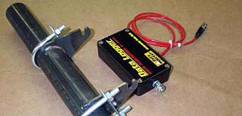
7. Wiring the power harness: Connect the red wire to 12 volt positive and the black wire to the battery ground. Connect the "chassis" lug or gray wire (on the rear of computer) to a separate chassis ground (not the same ground as the black wire) using 16-gauge wire or larger. This provides a shield for signal cables.
8. Position EGT cables clear of all other wiring for best noise isolation. (avoid spark plug wires or any ignition wiring).
 |
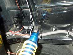 |
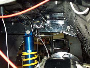
| The shock travel sensors are mounted in such a way that they have adequate capacity to measure the complete range of suspension travel. As you can see in this photo, one off the sensors is mounted on aspecially fabricated bracket, which affixes it to the chassis. A similar bracket is mounted on the driver's side of the car. | 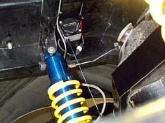 |
9. The accelerometer needs to be mounted solid and level. Vibrations in the mount will produce noise in the readings.
| The accelerometer is designed to be mounted solid to the chassis or affixed to the roll cage. Typically a bracket such as this is fabricated to mount the unit on the bar behind the driver seat. Auto Meter points out that if the mount is not strong enough to prevent flexing, then the accelerometer will see vibrations and can provide distorted acceleration readings. There's more too: The accelerometer must be mounted so that the face is directed toward the front of the vehicle. The unit must also be mounted perpendicular and level to the ground. There should be sufficient room in the mount so that the accelerometer can rotate 180 degrees in the brackets for calibration. After the accelerometer has been mounted, simply plug the connector into the ACC port on the rear of the computer. | 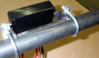 |
 |
|
 |
10. Installation in a magneto-fired application requires a shielding enclosure for the computer. Some applications may require shielding at the pressure sensor as well. These enclosures need to be constructed of steel material. Aluminum or stainless steel do not provide sufficient absorption of EMI radiation.
For a closer look at the installation process, have a peek at the accompanying pictures. Much of the work is simple, but remember, there's definitely a right and wrong way to install sophisticated electronic hardware.
Auto Meter Products Inc.
413 West Elm Street
Sycamore, IL 60178
PH: 815-895-8141
Thanks to Mike Pustelny Racing for sharing installation photos:
MPR Race Cars
5851 Scotch Settlement Road
Almont, Michigan 48003
PH# 810-798-8998
Copyright 1999-2004, Drag Racing Online and Racing Net Source