![]()
Project Muscrate
It's ALIVE!! Well, almost!!
by Jay Roeder
7/7/04
![]() ow, I can't
believe it is already June! I have been REAL busy lately building engines for
my customers and while that is a good thing from a business standpoint, it has
made it rather difficult to get as much done as I want to on MY engine. Responsibility
can be a real pain sometimes, ha, ha! Anyway, away we go!
ow, I can't
believe it is already June! I have been REAL busy lately building engines for
my customers and while that is a good thing from a business standpoint, it has
made it rather difficult to get as much done as I want to on MY engine. Responsibility
can be a real pain sometimes, ha, ha! Anyway, away we go!
This month I will share some of the thought process that goes into determining the specifications of my custom camshaft made by Comp Cams for Muscrate, and briefly cover some of the steps of the mysterious process know as "degreeing in the cam". Finally, the engine will be done!
At my shop, Roeder Performance Machine, I use Comp Cams almost exclusively for my custom camshafts, lifters, valvetrain, etc. One of the best things Comp has in its favor over other companies is the people that work there, in particular, Chris Padgitt. I have been doing business for many years with Chris, formerly at Lunati, and he is a wealth of knowledge on basically everything in a racing engine. I'm telling you this not because I think everyone should call Chris, but because the personal service you receive at Comp Cams is the difference. All of the major cam grinders have basically the same equipment, but Comp has some equipment and lots of database that other companies just don't have.
The first step in ordering a camshaft, either custom or "off the shelf" is to be realistic about the rest of the combination and its limitations. In the case of Muscrates 302, it is a 9.5:1 compression, 310 cube, 217 cfm intake flowing, single 4 barrel HEMI EATER! The point is that it is not going to make gobs of low end torque due to its size, and it is probably not going to make gobs of horsepower above 6500 rpm due to the head flow. So, I am aiming for a power range of something like 4500-6500 rpm. I am limited by IHRA rules to .498" valve lift and it is a hydraulic roller-type cam. Based on previous experience, I know that you can definitely hurt performance by over-camming an engine.
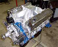 Ahh. The finished piece! 310 cubes of Hemi eater! This thing is in the need of a RACE CAR! |
Although Muscrates 302/320hp "crate motor" is not a typical "stocker" engine, a lot of the same thinking applies. For instance, the Performance Trends Engine Analyzer Pro dyno simulation program I used to run through some different ideas shows that this engine will make best peak horsepower with a duration profile of 266^ intake and 272^ exhaust at .050". That would be cool if we raced dynos. We don't. I ran numerous simulations in the program, changing duration, lobe separation, cam centerline advance and retard, etc., and came up with the best average horsepower and torque numbers the computer could muster. Then, I added a little experience and went through the Lobe Specifications section of the Comp Cams catalog and found the lobes that most closely matched. I called Chris and discussed what I wanted and told him what I had come up with. He amazingly said he thought what I found would work great, at least it would be a good starting point, and I had the custom ground cam to my door in three days. That is another service Comp has that no one else can beat.
So, what did I end up with? Well, part of building a "stocker" engine is not sharing ALL of your secrets. I know, you would like to poke me with a sharp stick right now, but that's the way it works. I don't make the rules! I can give you a good idea of the specs. The duration at .050" lobe lift is somewhere between 245^ and 255^ on both lobes, the lobe separation is 108 degrees, and the lobe lift is .312". (.312" x 1.6 rocker ratio equals .499" valve lift.) Hey, until I run the car I won't even know for sure if it will work!
Now for the "black art" of degreeing in the camshaft. Actually, it is a pretty straightforward operation that MUST be performed on any engine you care about making power. Basically, when you degree in a camshaft you are simply making sure the valves open and close when they are supposed to relative to the position of the piston. All cams come with a spec. card that will tell the opening and closing events of that particular cam. Some companies list the specs. differently than Comp but the way I prefer to degree the cam is by using the opening and closing events of the cam at .050" lobe lift. Keep in mind that lobe lift and valve lift are completely different things. Lobe lift is how far the lifter will move from a resting position (base circle) and valve lift is your rocker ratio (mine is 1.6) multiplied by lobe lift. The reason or reasons it is important to degree in the cam is because there are lots of variables that can affect the actual cam timing. For instance, has your block been line bored? If so, you have probably loosened up the timing chain slack because of the now shorter distance between the crankshaft and camshaft centerlines. This may easily be 1 degree of retard.
Next, what quality of timing set did you buy? Some of the cheaper sets can easily be off in dowel hole placement 2-3 degrees. How about the crankshaft keyway? And for that matter the crank key itself? Does the key fit snugly in the slot or is it kind of rolled over? And, believe it or not, that shiny new camshaft may not have the dowel hole in exactly the right spot. All of those variables and more are why you must have the cam degreed in. Also, this is why most companies such as Comp Cams "build in" approximately 4 degrees of advance. In the case of someone who just lines up the timing dots and hopes for the best this is a built in cushion to hopefully lesson the effects of the aforementioned variables. A retarded camshaft will give lazy engine response and take away bottom end torque.
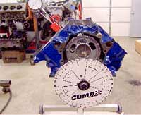 Here is the Comp Cams degree wheel in action. The dial indicator is set up on the intake lifter. Degreeing in the cam is part of what sets apart the engine assemblers from the PRO engine builders. |
Now, a brief overview of the actual process of degreeing in a cam. I am only going to explain the duration at .050" lobe lift method. The other method is to find the intake centerline but I don't like that method, so there! Install your timing set with everything on theoretical "straight up". First, you have to have the proper equipment for the job. You will need a dial indicator and magnetic base, a degree wheel such as the one from Comp Cams, a pointer (a piece of 10 gauge wire and a bolt to fasten it works fine) and a positive piston stop. The stop can be a homemade plate with a stop bolt or a "fancy" one like the piece I use from Powerhouse Products. Second, fasten the degree wheel to the snout of the crank with the number one piston at approximately top center and position the degree wheel "0" at the 12 o'clock position. Now back down the piston about a half inch in the bore (doesn't matter clockwise or counterclockwise) and install the positive stop. The photos will show this more clearly.
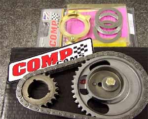 Here is the Comp Cams Hex-a-just timing set and torrington bearing camshaft retaining plate. They are both top quality pieces and make my job just a little easier. The retaining plate replaces the factory plate with a bearing. |
Then rotate the piston back up very gently until it stops against the piston stop. Take your attached pointer and line it up on some even number such as 20 degrees. It doesn't matter what number you line up on, it just makes it easier to figure with even numbers. Place a mark on the wheel at that point with a pen. Then, rotate the piston back down to bottom center and keep going until you once again come up against the stop. Mark that position on the wheel and add up the amount of degrees between the two marks. Let's just say that it all worked out perfect and both of your numbers were 20 degrees. One side is before top center and the other is after top center. If you add the two values you get 40 degrees total. Divide 40 by half and you get 20. So, in this case your TRUE top dead center would be on the 0-degree mark on the wheel. Whatever the numbers are, add them and divide by two. Then count back from one of the marks the amount you came up with. This is TDC.
Next, remove the piston stop and rotate the crank until the new true TDC mark lines up with the pointer. If the new TDC mark is for instance 5 degrees before TDC on the wheel, line that up with the pointer. Then move the POINTER to TDC "0" on the wheel. DO NOT move the wheel to match the pointer. That would ruin all your efforts. Now, we can get
|
ADVERTISEMENT  |
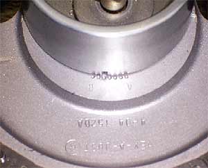 This is attempting to show the degree notches that are used for advancing or retarding the cam timing. Instead of removing the crank sprocket or using small offset bushings you simply rotate the eccentric to the desired position. NICE! |
The last thing I want to touch on is valve clearance. Not having enough can be very bad! I simply cannot emphasize enough the importance of checking valve clearance. Once you have the cam put in its place, assemble a cylinder head with light checking springs on one chamber and install it with an old gasket of the same approximate thickness as the ones you will use. Drop in the pushrods and rocker arms you will be using and set a dial indicator up to read the travel of the valve retainer. Now rotate the engine over carefully and with your hand gently push down on the rocker arm tip where it contacts the valve stem. Doing this at different points along the way you will find the point of closest clearance and know what you have. The correct amount depends on many variables so a call to a reputable engine builder or cam company would be wise. The generally accepted clearance would be .080" minimum. I have some engines running with only .035" clearance but that is not normally desired. It's a rules thing. The design of your valve springs and installed seat pressure can also have dramatic effects on performance, especially when the valve clearances become tighter. I helped a customer with a BBC last year pick up .15 seconds and almost three mph simply by increasing spring pressure. Once again, there is no one perfect pressure for every combination. It is a matter of trial and error, but I always lean towards what some people would call the "over-sprung" end of the spectrum. I have not seen an example yet where too much spring made less power. Unless of course you have a flat tappet cam and wipe the lobes off! Ha, ha!
Here we see the bottom end with windage tray/scraper
and the factory Ford oil pump and pickup tube. CUTLINE: This is attempting to
show the "spider" tray that keeps the hyd.roller lifters in place. Also, the
Ford Performance head gasket.
Well, the pictures will tell the rest of the story and I am REALLY looking forward to finally getting back on the track! Not racing just plain SUCKS! Next issue I will cover the fuel and ignition systems along with intake manifold selection and hopefully have some actual track results!
Remember, life's too short.
When in doubt, DO A WHEELIE!! ![]()
| Sources | ||
| Roeder Performance Machine 1009 Bronson Ave. SE Waverly, IA 50677 www.roederperformancemachine.com (319) 352-2220 |
||
Copyright 1999-2004, Drag Racing Online and Racing Net Source