CHECK YOUR FLUIDS
Think of a torque converter as a miniature transmission
with an infinite number of gears between idle and
near 1:1 efficiency at full throttle. The torque
converter accomplishes this task through the miracle
of fluid dynamics. The classic analogy used to
explain the basics of torque converter operation
is that of two fans facing each other. With one
fan on and the other off, both sets of fan blades
will spin. The blades of the turned off fan are
being driven by the energy created by the one turned
on. The transmission fluid inside a torque converter
behaves the same way as the air between the fans.
One fan is connected to the engine. The other fan
is connected to the transmission. Between the two
fans is transmission fluid. While the two fans
analogy goes far to explain the operation of a
fluid coupling, it is really only two-thirds of
the story of a torque converter.
PARTS AND PIECES
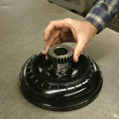
There are four parts of a torque converter that
together function as a whole. Working from the
crankshaft back the first part is the cover. The
cover houses the torque converter and is connected
directly to the crankshaft by way of the flexplate.
Welded to the back of the cover is the driving
member of the converter – or the impeller.
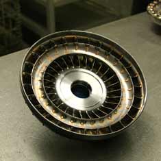
Since the impeller is physically connected to the
cover it always spins in direct relation to the
crankshaft, and also drives the fluid pump in the
transmission. The driven part of the converter
is the turbine. The turbine spins inside the cover,
and is connected directly to the input shaft of
the transmission. The fluid energy created by the
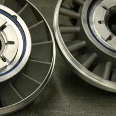
impeller spins the turbine. In between the impeller
and the turbine is the thinking part of the torque
converter – the mighty stator – or
reactor. The stator alters the flow of fluid between
impeller and the turbine, and is the key to the
infinite flexibility of converter operation. The
stator creates the multiplication of torque by
redirecting fluid as it flows from the center of
the turbine.
FLUID COUPLING
Power applied to a direct fluid coupling, such
as a turbine and impeller with no stator, would
quickly bring the coupling to the point where the
two parts and the fluid are rotating as a solid
mass. This is known as the coupling phase, or the
point where the turbine is turning 9/10ths as fast
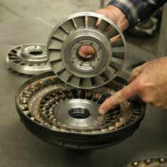
as the impeller. The fins inside the impeller and
turbine force the fluid in two directions at once
to achieve this coupling. The fluid flows in a
rotary and vortex motion at the same time. Rotary
flow forces the fluid to the outside of the impeller
and turbine, and creates a centrifugal force that
rotates the assembly. Vortex flow, created by the
blades and channels fluid in a vortex within the
impeller and turbine. This forces the fluid to
circulate from the outside and back through the
centers of the turbine and impeller. At the coupling
stage – at 9/10ths, rotary flow overcomes
vortex flow and the two halves spin essentially
as one. |