|
|

|
 |
 |
 |
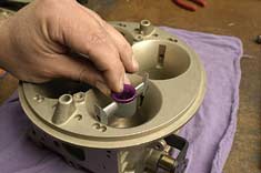
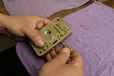
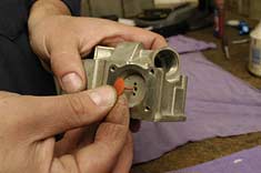
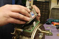
| The boosters are the key to the amplification of
the venturi signal and optimal fuel atomization. Changes made here
help tailor the atomization of fuel according to engine demand. |
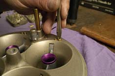
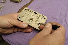
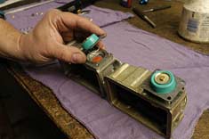
After the vent tubes and shooters go into
place, the air bleeds are installed. Altering airflow to the circuits
here affects the pre-atomization of fuel as it exits the metering
block, and before it enters the throttle body. The outboard screws
are for idle, the middle for the intermediate circuit, and the inners
are for the high-speed circuit. |
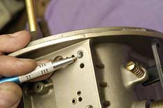
Tough heli-coil steel thread replacements
are substituted in for the soft metal stock threads of the throttle
body. No surprises here. |
 |
 |
 |
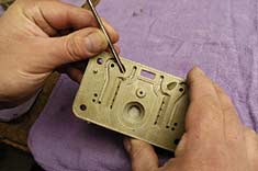
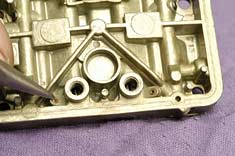
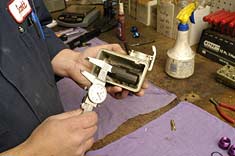
| A tapered reamer is used to clean up the
machining or resize the main well. Different-sized tapers not only
clean up the stock machining, but also allow for different rates
of fuel flow through the main well. |
The idle fuel pickup goes into the metering
block. This tube picks up fuel from the main well and delivers it
to the idle circuit, hence its name. |
A pin drill is used to modify the emulsion
wells. The entire main circuit fuel curve can be shaped by changing
the size of these channels, as air from the bleed screws pierces
into the fuel emulsion to pre-atomize the fuel before it reaches
the boosters. Top-end horsepower can be found here. |
 |
 |
 |
| Fuel metering for the intermediate circuit
is altered by the addition of these brass restrictors. |
Jet extensions prevent sloshing fuel from
uncovering the jets during launch. The vent tube at the top of the
metering block prevents the same slosh from stopping air flow. |
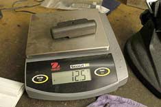
Each nitrophyl float is scaled out and only
perfectly matched sets are installed for added consistency of fuel
delivery. |
 |
 |
 |
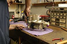
| Next up are the fuel bowls and accelerator
pumps. The umbrella valve only allows fuel to flow one way to the
shooters when the accelerator pump is active. |
The accelerator-pump diaphragms are literally
the heart of the system, pumping fuel through the shooters and into
the engine on throttle application. |
Float height is set on the bench before final
assembly and engine testing. |
 |
 |
 |
| Non-stick gaskets go in-between the metering
block and the fuel bowls and the whole thing is buttoned up. |
The accelerator-pump linkage is calibrated
before engine testing. Any slop here makes for a severe dead spot
in throttle response. |
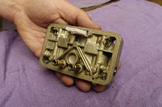
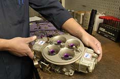
The finished product! Every E-Carb Holley
is live-engine-tested. Each T/S-1050 Dominator is run up against
a converter on a transbrake. Final idle adjustment is made. Float
levels are set. Accelerator-pump operation is checked and the carburetor
is tested for leaks before it's put into the box. |
| SOURCE |
E-Carb Competition Carburetion (A division of
Evergreen Carburetors)
www.ECarb.com
12432 Highway 99 South, Unit 77
Everett, WA 98204-5505
Phone: (888) 259-2272 |
|
 |